


 0
0
 0
0
Your basket is empty...
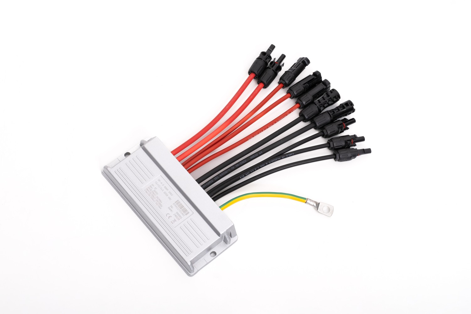
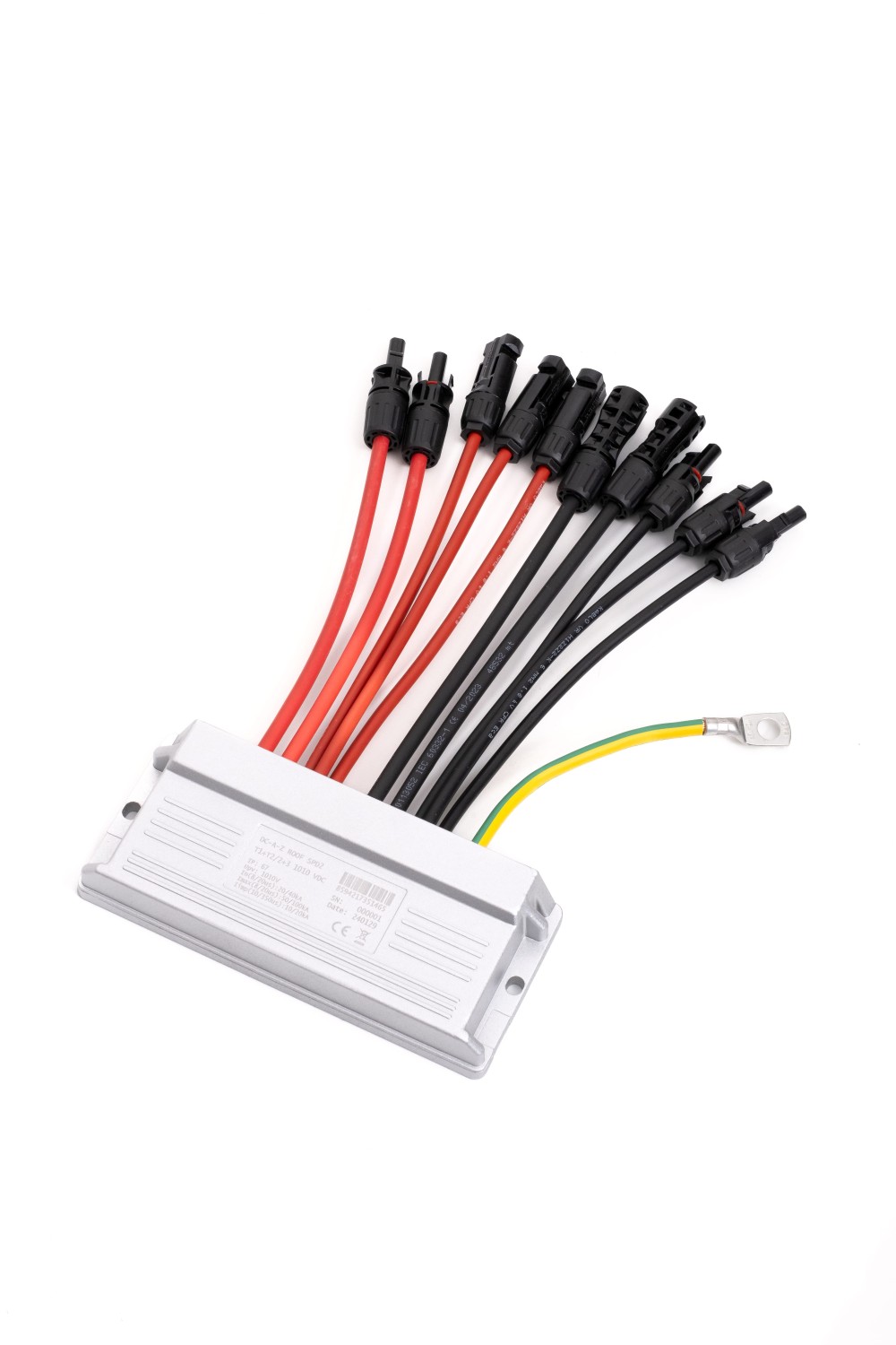
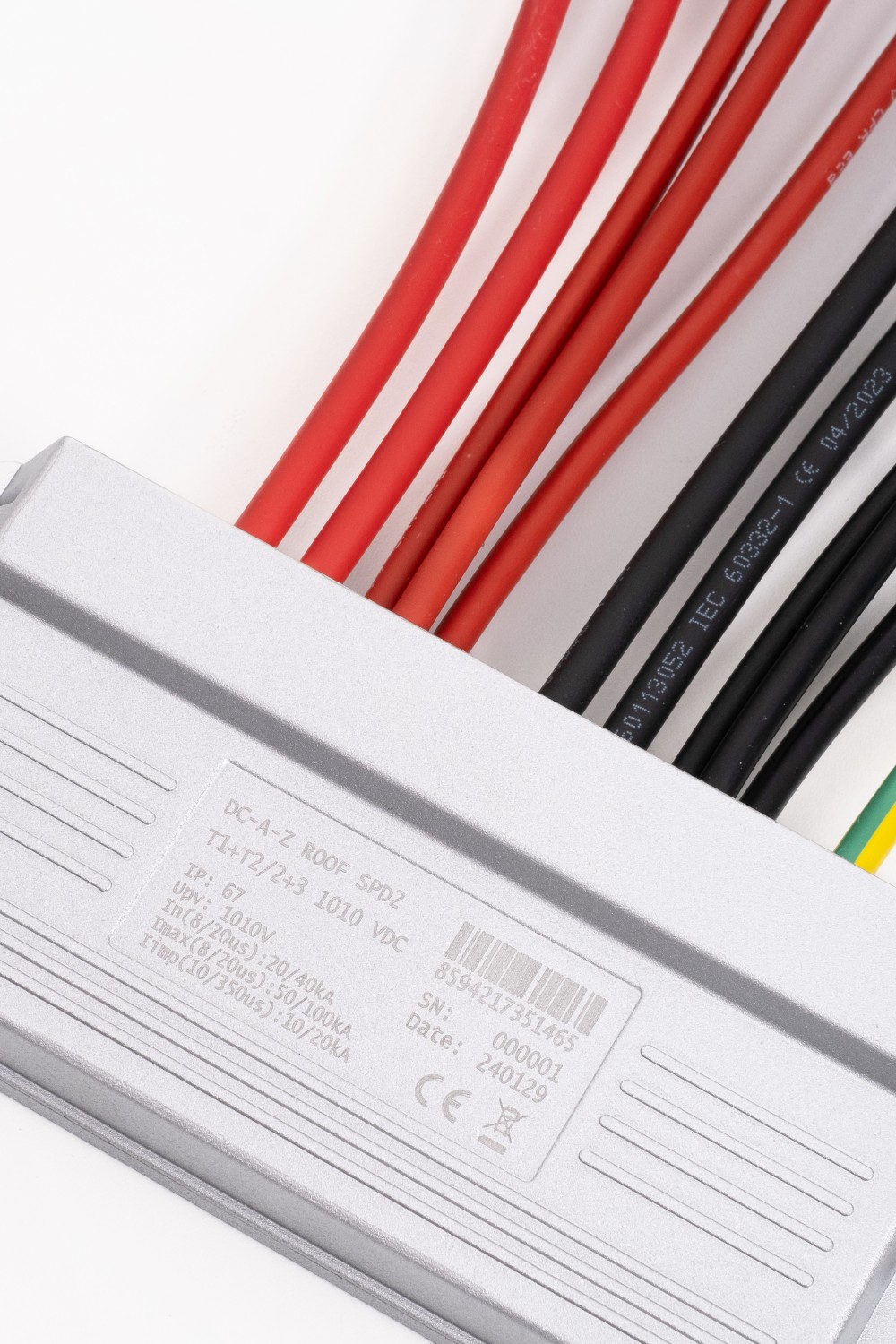
A-Z ROOF SPD2 T1+T2 2+3 1010 VDC
EAN: 8594217351465
SKU: DC2-3+2
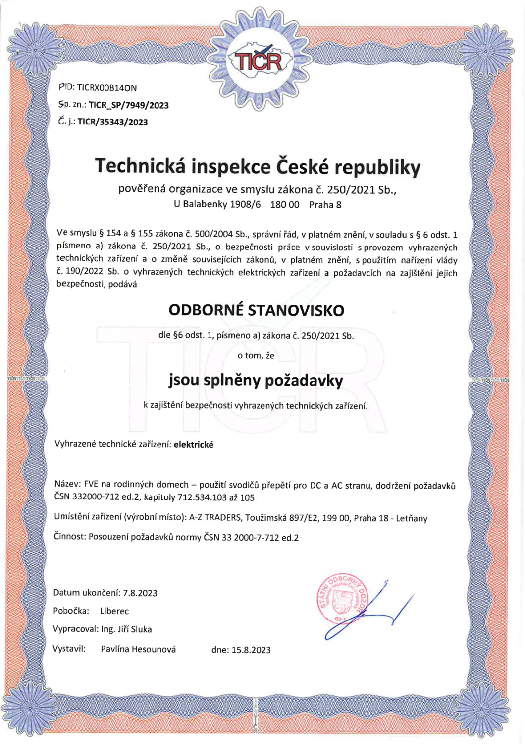
Due to the regulatory obligation to place class 1 surge arresters near the downfall of string wires into the building, we are introducing a new model line of SPD units for mounting on the supporting structure of the photovoltaic panels themselves.
Prices are visible only to registered users.
PRODUCT DESCRIPTION
 Product description
Due to the regulatory obligation to place class 1 surge arresters near the downfall of string wires into the building, we are introducing a new model line of SPD units for mounting on the supporting structure of the photovoltaic panels themselves.
The actual construction, taking into account weather conditions and the method of assembly, is made of aluminum alloy (the same material as the supporting profiles of PV panels - there is no risk of electrochemical corrosion) with hermetically sealed internal circuits in polyurethane material with an inert filler that suppresses combustion.
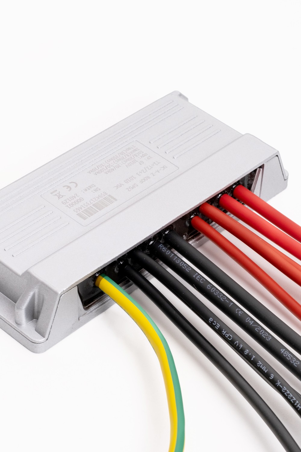
The unit is designed as a through-type unit for easy implementation into a string - both poles of the string are connected to the unit and both of them also exit. The connection is made with classic MC4 connectors (with an integrated fuse at the input) and wires with a cross-section of 6 mm 2 (in some versions even 10 mm 2 ) with double insulation and color coding.
The connection of the PE conductor or the connection with the LPS elements is solved on the box chassis itself using an M10 (M8) screw through a pressed-in eye on a stranded conductor >16 mm 2 or directly via a T-screw by connecting to the supporting structure/LPS downpipe, or in combination.
The SPD unit itself is of class T1 + T2, which means that due to the above-standard leakage resistance (12/25 kA), it can also be applied to centers with less than 4 down conductors (according to ČSN EN 51643-32).
Due to the specific design and location, it is necessary to measure the residual current at the maximum operating voltage after each interruption of the integrated fuse (due to the action of the SPD).
If the value is higher than the maximum value specified by the manufacturer, the entire SPD module must be replaced. An indication of a blown fuse is the absence of voltage on the string circuit after the SPD module.
| Property | Value |
|---|---|
| Maximum operating DC voltage between L+ and L- (L+- and PE) | 1010 V |
| I n (8/20 μs) | L+ or L- /PE 20 kA L+- /PE 40 kA |
| I max (8/20 μs) | L+ or L- /PE 50 kA L+- /PE 100 kA |
| I mp (10/350 μs) | L+ or L- /PE 12.5 kA L+- /PE 25 kA |
| Dimensions | 234x126x34.4mm |
| Connecting wires | Length: approx. 25 cm; Cross-section: 6/10 mm 2 ; Connectors: MC4 male/female with integrated fuse |
| Location | Outdoor - installation on the supporting system of PV panels |
| Rated short-circuit current I scpv | 10 kA |
| External disconnectors | fuse integrated in MC4 < 30 A at input |
| Indication of SPD effect | output voltage drop to 0 V |
| Residual current | max 50 μA |
| Classification according to ČSN EN 61643-11 ed. 2 and ČSN EN 61643-31 | T1+T2 |
| Suitable for network | DC |
| Rated load current I L | Type 1 - 30 A Type 2 - 30 A Type 3 - 80 A |
| Short circuit resistance I SCPV | 10 kA |
| Voltage protection level at In U P | < 2.3 kV |
| Response time t A | < 25 ns |
| Case material | Aluminum alloy |
| Degree of protection of the cover | IP67 |
| Working temperature ϑ | -40 ÷ 85 °C |
| Humidity range R H | 0 ÷ 100% |
| Cross section of the connector wire | Cross-section: 6 mm 2 / 10 mm 2 (according to design) |
| Earth terminal tightening torque | According to the M8/10 screw used |
| Method of assembly | FV Alu profile |
| Working position | Any |
| SPD fault mode | OCFM |
| Interchangeable design | NO |
| Service life | > 15 years |
SUBSCRIBE NEWSLETTER
Newsletter
QUERY
