


 0
0
 0
0
Your basket is empty...
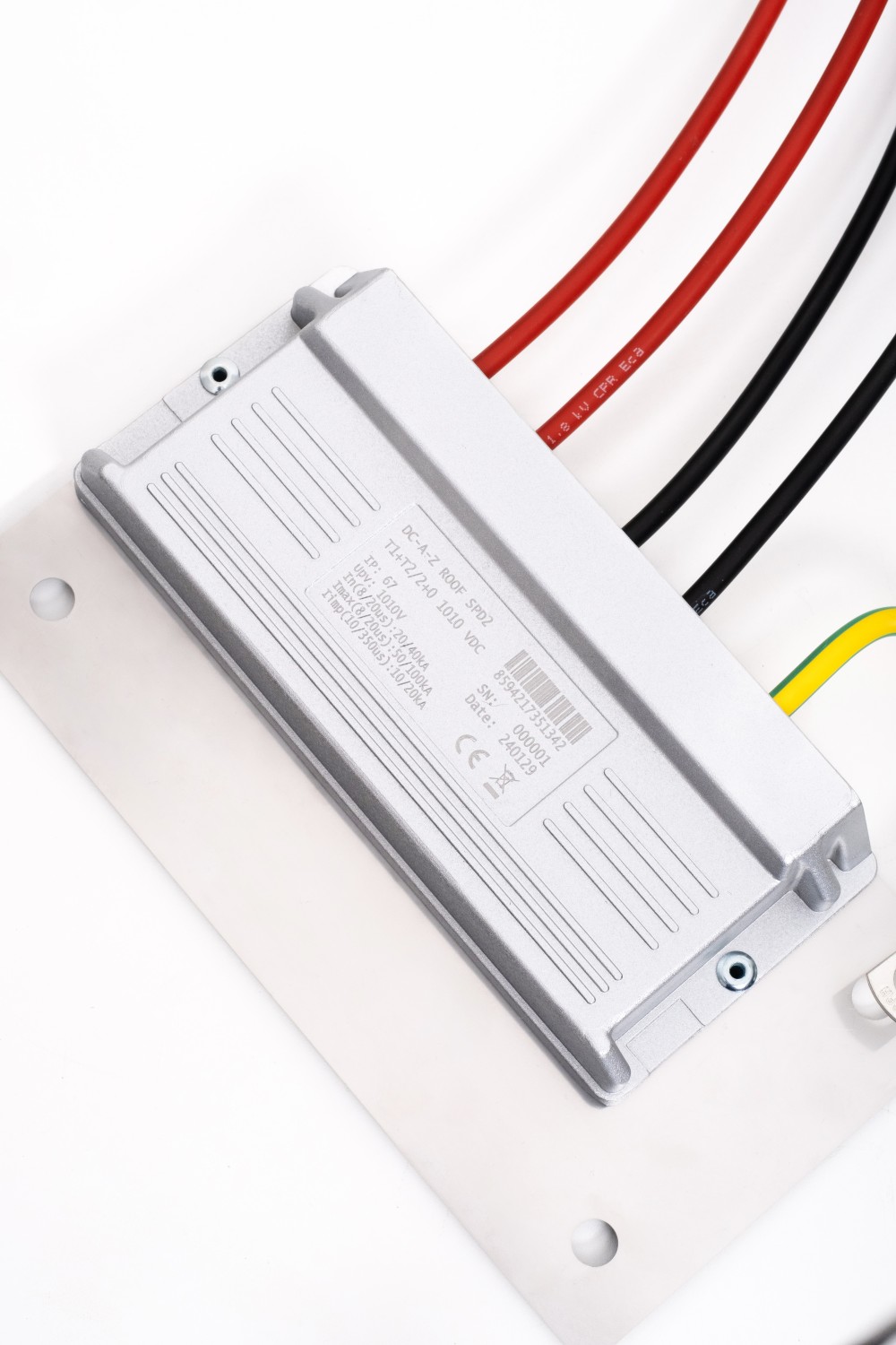
A-Z ROOF SPD T1+T2 2+0 1010 VDC
EAN: 8594217351342
SKU: DC-2
Due to the normative obligation to place class 1 surge arresters near the discharge of string wires into the building, we are introducing a new model series of SPD units for mounting on the supporting structure of the photovoltaic panels themselves.
Prices are visible only to registered users.
PRODUCT DESCRIPTION
 Product description
Due to the normative obligation to place class 1 surge arresters near the discharge of string wires into the building, we are introducing a new model series of SPD units for mounting on the supporting structure of the photovoltaic panels themselves.
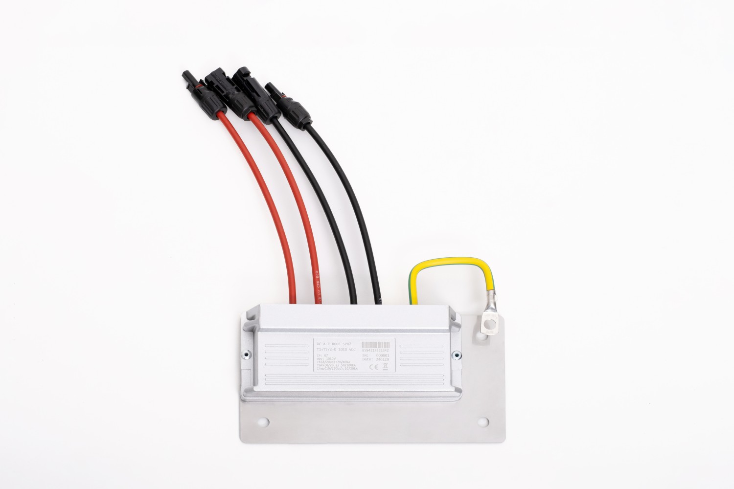
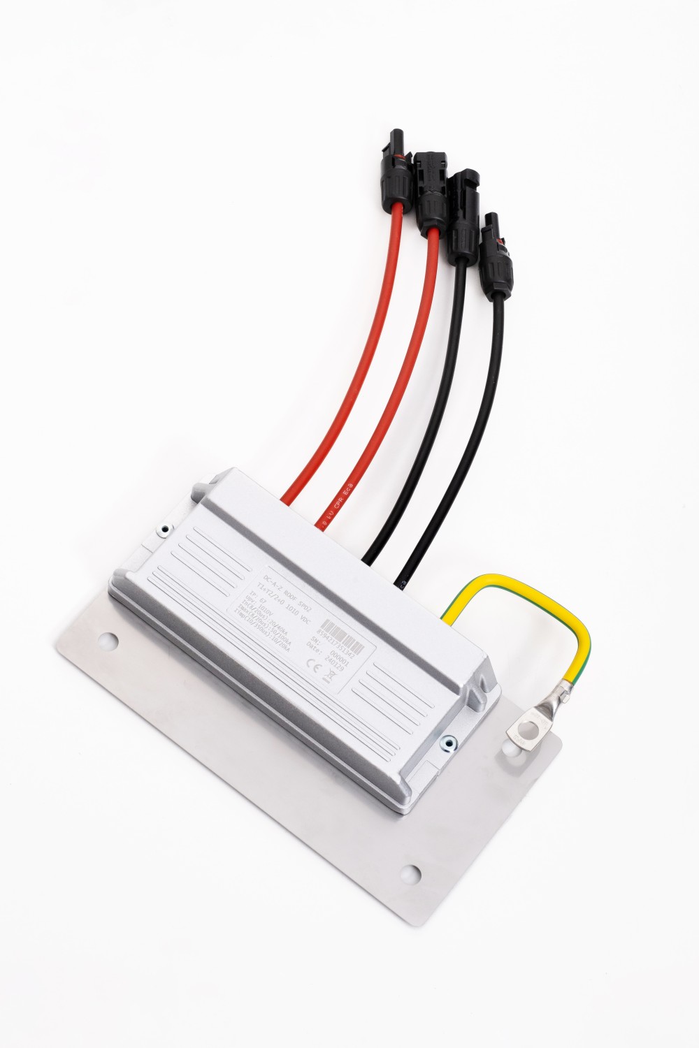
The construction itself is made of aluminum alloy (the same material as the supporting profiles of the PV panels - there is no risk of electrochemical corrosion) with hermetically sealed internal circuits in polyurethane material with fire-suppressing internal filler, taking into account the weather conditions and the method of assembly.
With regard to easy implementation into a string, the unit is realized as pass-through - both poles of the string are connected to the unit and both of them also exit. The connection is made with classic MC4 connectors (at the input with an integrated fuse) and wires with cross-sections of 6 mm 2 (in some versions also 10 mm 2 ) with double insulation and color resolution.
The connection of the PE conductor or the connection to the LPS elements is solved on the box's own chassis using an M10 (M8) screw through a crimped eye on a cabled conductor >16 mm 2 or directly via a T-screw by connecting to the support structure/LPS lead, or in combination.
The SPD unit itself is of class T1 + T2, where, due to the above-standard leakage resistance (12/25 kA), application is also possible to centers with less than 4 discharges (according to ČSN EN 51643-32).
Due to the specific design and location, it is necessary to measure the residual current at max. operating voltage.
If it is higher than the maximum value specified by the manufacturer, it is necessary to replace the entire SPD module. An indication of a fuse break is the absence of voltage on the string circuit behind the SPD module.
| Property | Value |
|---|---|
| Maximum operating DC voltage between L+ and L- (L+- and PE) | 1010 V |
| In (8/20 μs) | L+ or L- /PE 20 kA L+- /PE 40 kA |
| I max (8/20 μs) | L+ or L- /PE 50 kA L+- /PE 100 kA |
| I mp (10/350 μs) | L+ or L- /PE 12.5 kA L+- /PE 25 kA |
| Dimensions | 234x126x34.4mm |
| Connecting wires | Length: approx. 25 cm; Cross section: 6/10 mm 2 ; Connectors: MC4 male/female with integrated fuse |
| Location | Outdoor - mounting on the PV panel support system |
| Rated short-circuit current I scpv | 10kA |
| External disconnectors | fuse integrated in MC4 < 30 A at input |
| Indication of SPD impact | output voltage drop to 0 V |
| Residual current | max 50 μA |
| Classification according to ČSN EN 61643-11 ed. 2 and ČSN EN 61643-31 | T1+T2 |
| Suitable for network | DC |
| Rated load current I L | Type 1 - 30 A Type 2 - 30 A Type 3 - 80 A |
| Short circuit resistance I SCPV | 10kA |
| Voltage protection level at In U P | < 2.3 kV |
| Response time t A | < 25 ns |
| Case material | Aluminum alloy |
| Enclosure protection level | IP67 |
| Working temperature ϑ | -40 ÷ 85 °C |
| Humidity range RH | 0 ÷ 100% |
| Connector wire cross-section | Cross section: 6 mm 2 / 10 mm 2 (depending on version) |
| Earth terminal tightening torque | According to the M8/10 screw used |
| Mounting method | FV Alu profile |
| Working position | Any |
| SPD failure mode | OCFM |
| Interchangeable design | NO |
| Lifespan | > 15 years |
SUBSCRIBE NEWSLETTER
Newsletter
QUERY
